

Pneumatic Control Valves: Components, Common Faults, and Troubleshooting Techniques
Pneumatic Control Valves: Components, Common Faults, and Troubleshooting Techniques
Introduction
Pneumatic control valves play a critical role in industrial automation by offering precise regulation of fluid and gas flow. These China Control Valves convert air pressure into mechanical motion, allowing for efficient and responsive flow control in applications ranging from chemical processing and power generation to water treatment and HVAC systems.
To maintain high performance and minimize downtime, it is essential to understand the internal workings of pneumatic control valves, identify common faults, and apply systematic troubleshooting techniques.
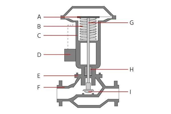
Anatomy of a Pneumatic Control Valve
A pneumatic control valve comprises several integral components working together to achieve accurate flow control. Below is a breakdown of each major part and its function:
1. Actuator (A)
The actuator transforms compressed air into mechanical movement, adjusting the valve stem and plug to control flow. There are two main actuator types:
-
Diaphragm Actuators: Suitable for low-pressure applications, offering fast response.
-
Piston Actuators: Better for high-pressure scenarios due to their robust construction.
Actuators can be:
-
Single-Acting: Air pressure moves the actuator in one direction; a spring returns it to the original position during failure.
-
Double-Acting: Uses air pressure in both directions, providing enhanced control and no reliance on a spring.
2. Spring (B)
In single-acting systems, the spring provides a fail-safe mechanism. It returns the valve to a safe default position (fail-open or fail-closed) when air pressure is lost—critical for process safety.
3. Yoke (C)
The yoke is the structural link between the actuator and the valve body. It ensures precise alignment and absorbs mechanical stress during valve operation, especially in larger or high-pressure systems.
4. Positioner (D)
The positioner ensures the valve reaches the exact position commanded by the control signal. It enhances precision and responsiveness. Types include:
-
Pneumatic Positioners: Controlled via air signals.
-
Electro-Pneumatic Positioners: Accept electrical signals and convert them to pneumatic output.
-
Digital Positioners: Offer advanced diagnostics, signal interpretation, and high-accuracy feedback.
5. Bonnet (E)
The bonnet houses the valve stem and protects internal parts. It must maintain a pressure-tight seal and provide thermal and mechanical stability.
6. Valve Body (F)
The main housing that contains the seat and plug. Body types vary by application:
-
Globe Valves: Best for throttling and fine control.
-
Ball Valves: Quick shut-off, minimal pressure drop.
-
Butterfly Valves: Ideal for large flow rates and low pressure.
-
Gate Valves: On/off control for straight-line flow systems.
7. Valve Stem (G)
Connects the actuator to the internal plug or disc, transferring motion for valve actuation. It must withstand torsional and axial stresses without compromising seal integrity.
8. Seals and Gaskets (H)
Ensure air and process fluids remain contained. These parts are prone to wear and require regular inspection to prevent leakage and pressure loss.
9. Valve Seat and Plug (I)
These elements directly control flow. The plug modulates flow by moving relative to the seat. Material and machining precision are key to leak-free operation and longevity.
Common Pneumatic Control Valve Faults
Even with robust design, pneumatic control valves may develop faults over time. Understanding these issues is essential for timely repair and system reliability:
1. Air Leaks
Result from worn seals, cracked hoses, or loose fittings. Leaks reduce actuator power and cause sluggish valve movement or failure to actuate.
2. Sticking or Jamming
Caused by rust, debris, or misalignment within the valve stem or plug. It can lead to inconsistent operation, reduced control accuracy, or complete valve failure.
3. Actuator Failure
Results from diaphragm rupture, piston wear, or mechanical damage. An actuator stuck in one position can disrupt entire control loops.
4. Positioner Malfunction
Leads to incorrect valve positioning and poor process control. Can be due to signal drift, internal wear, calibration errors, or pneumatic/electrical faults.
5. Seal Degradation
Worn or chemically damaged seals allow leaks of process media or air, reducing efficiency and creating potential safety hazards.
Troubleshooting Techniques
A methodical approach to troubleshooting enhances diagnosis speed and ensures accurate repairs. Follow these steps:
1. Review Maintenance History
Look for trends or recurring issues. This can help identify systemic problems or components nearing the end of their service life.
2. Visual Inspection
Inspect for visible signs of damage, corrosion, fluid leakage, or misaligned parts. External signs often point to internal issues.
3. Verify Air Supply
Check supply pressure using a calibrated gauge. Ensure that lines, fittings, and regulators are clean, intact, and leak-free.
4. Test the Actuator
Manually operate or isolate the actuator to check its responsiveness. Listen for air leaks or hissing sounds, indicating failed diaphragms or seals.
5. Calibrate the Positioner
Follow manufacturer instructions to recalibrate the positioner. Ensure correct feedback loop operation and eliminate electrical or pneumatic signal interference.
6. Check Control Signals
Use a multimeter or loop tester to confirm the integrity of electrical signals. Check wiring, grounding, and power supplies.
7. Perform Manual Movement
Operate the valve manually to detect stiffness, grinding, or resistance. This test can help isolate internal blockages or mechanical faults.
8. Internal Inspection
Disassemble the valve if needed to check stem alignment, plug wear, seat damage, or buildup of deposits. Clean or replace as necessary.
9. Evaluate Pipeline Conditions
Downstream obstructions or backpressure may affect valve performance. Inspect pipeline sections for fouling, clogging, or corrosion.
Conclusion
Pneumatic control valves are indispensable in modern process control systems, offering fast and accurate modulation of gas or fluid flow. While their design is reliable, they are not immune to operational faults. Familiarity with their components, common failure modes, and troubleshooting methods allows for rapid diagnostics and corrective action.
By implementing a proactive maintenance strategy and following structured troubleshooting practices, industrial operators can reduce downtime, extend equipment life, and maintain optimal performance of pneumatic control systems.Know more about Google SEO Directory