


Best Practices in Solvent Extraction Plant Layout
The solvent extraction process is a marvel of chemical engineering, transforming crude VGO into refined base oil. But the efficiency of this transformation isn’t determined by chemistry alone. The physical layout of the plant plays a monumental role in operational safety, maintenance accessibility, energy efficiency, and long-term operational cost. A poorly laid-out plant is a constant source of bottlenecks, hazards, and downtime.
Moving beyond the P&ID, here are essential best practices and guidelines for designing an optimal solvent extraction plant layout.
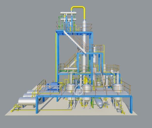
1. The Safety Imperative: Zoning and Containment
Solvents like NMP, Furfural, and Phenol require meticulous handling. Safety must be the primary layout driver.
Process Zoning: Clearly segregate areas into zones: Extraction & Recovery Unit, Solvent Storage, Utilities, and Tank Farm. Implement positive physical boundaries or spacing between them.
Containment: Design the unit, especially around pumps, exchangers, and column tie-ins, with proper drip trays and curbed containment basins (bunds) to prevent soil and water contamination in case of a leak.
Ventilation: Ensure the extraction and recovery sections are in well-ventilated, open-air structures to prevent the buildup of solvent vapors. Enclosed buildings require powerful, explosion-proof ventilation systems.
Access & Egress: Provide clear, unobstructed escape routes from all levels of the structure, particularly around major vessels and the heater.
2. Process Flow Efficiency: Minimizing Pressure Drop and Energy Loss
The goal is to enable smooth, thermodynamically efficient flow with minimal pumping energy.
Gravity is Your Friend: Position the Extraction Tower and Stripping Towers at an elevation that allows for gravity flow of the raffinate and extract streams between columns and to subsequent heaters or exchangers where possible.
Proximity Matters: Place the solvent recovery columns (e.g., Raffinate Stripper, Extract Stripper) and the solvent dehydrator as close as possible to the main extraction tower to minimize long, heat-traced transfer lines that represent both capital cost and energy loss.
Heat Integration Clustering: Group heat exchangers (e.g., feed/effluent exchangers, solvent/oil exchangers) into a structured pipe rack area. This simplifies piping, supports effective insulation, and facilitates future cleaning or bundling.
3. The Maintenance Mandate: Designing for Accessibility
If a technician can’t reach it, it won’t get maintained. Downtime is the enemy of efficiency.
Equipment Spacing: Adhere to minimum spacing guidelines (e.g., as per API standards) between vessels, pumps, and exchangers. This allows for mobile crane access, tube bundle pulling, and safe working space for hot work.
Lifting Beams & Monorails: Install permanent lifting beams above critical equipment like pump banks, filter housings, and exchanger bundles to enable safe, quick maintenance.
Platforms and Ladders: Design full-access platforms around all column manways, valve clusters, and instruments that require regular operation or inspection. Avoid "orphaned" valves that can only be reached by a mobile scaffold.
4. Utility Integration and Solvent Handling
Centralized Utility Corridors: Run steam, condensate, cooling water, and nitrogen lines along dedicated corridors on the pipe rack, with clear drop-down points to equipment. This simplifies tracing and insulation.
Solvent Storage Tank Location: Position the fresh and reclaimed solvent storage tanks in their own secured, contained area, downhill and downwind from the main process unit where practical. This reduces risk and pumping load.
Loading/Unloading Areas: Designate safe, well-ventilated areas for solvent delivery and sludge/extract removal, with clear traffic flow away from main process operations.
5. Future-Proofing and Flexibility
Modular Design: Consider a modular layout for sections like the solvent recovery system or dehydration section, which can allow for easier future capacity upgrades or technology swaps.
Space Reservation: Leave "blank" paved and piped spaces on the pipe rack and in the equipment plot for potential future add-ons, such as an additional heat exchanger for improved energy recovery or a pre-treatment module.
Conclusion:
An efficient solvent extraction plant layout is a three-dimensional chess game balancing process chemistry, mechanical engineering, and human factors. It goes beyond simply connecting vessels with pipes. By prioritizing safety through zoning, enhancing efficiency through intelligent equipment arrangement, and guaranteeing maintainability with generous access, you create a plant that is not only cost-effective to build but also safe, profitable, and sustainable to operate for decades. A great layout is the silent partner to a smooth-running operation.

 English
 Arabic
 Español
 Português
 Deutsch
 Türkçe
 Dutch
Dutch
 Italiano
 Russian
 Romaian