

The Telecentricity Trap: Solving Angular Measurement Errors in Conoscope Lens Integration
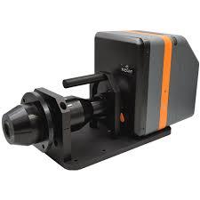
In the production of Micro OLEDs and foldable displays, the conoscope lens is the gatekeeper of quality. It is designed to map 3D angular light distribution onto a 2D sensor. However, as display pixels get smaller and viewing angles get wider, engineers are running into a critical problem: the measurement is distorting the product.
1. The Pupil-Side Telecentricity Failure
The most common problem with a standard conoscope lens setup is a lack of true telecentricity on the pupil side.
-
The Problem: In theory, the chief rays should be parallel to the optical axis. In practice, many lenses suffer from "pupil tilt" at high angles (above 60° to 70°).
-
The Result: This causes a "projection squeeze" where the angular resolution at the edges of the measurement circle is lower than at the center. If you are measuring the luminance uniformity of a VR waveguide, this error makes a perfect display look like it has "dim edges" when it actually doesn't.
2. The "Stray Light" Ghosting in High-Contrast Displays
With the rise of HDR and OLED technologies, the contrast ratios are reaching $1,000,000:1$. A major failure point for the conoscope is internal stray light (flare).
-
The Mechanism: Light from the bright center of a display reflects off the internal lens barrels or the edges of the Fourier transform lens elements.
-
The Failure: This light "washes out" the dark areas of the angular plot. For B2B suppliers, this is a nightmare because it results in "False Failures" during QC—the lens reports a lower contrast ratio than the display is actually producing.
3. Chromatic Shift at Extreme Angles
Because a conoscope lens must capture a massive Field of View (FOV)—often up to 160°—the light travels through the extreme periphery of the glass elements.
-
The Issue: Lateral Chromatic Aberration (LCA) becomes exponential at these angles.
-
The Impact: Red, green, and blue light components from the same pixel land on different pixels of the CCD/CMOS sensor. This creates a "false" color shift in the measurement data. Engineers often spend weeks trying to "fix" a display's color calibration when the problem is actually the refraction limits of the conoscope lens itself.
Technical Summary: Measuring the Measurer
| Measurement Challenge | Physical Cause | Impact on B2B Yield |
| Cosine Fourth ($cos^4 \theta$) Loss | Natural light fall-off at high angles | Underselling display brightness at wide angles. |
| Distortion Calibration | Non-linear Fourier mapping | Inaccurate "Sweet Spot" mapping for VR/AR. |
| Mechanical Alignment | Centration error in lens stack | Asymmetrical viewing angle plots (skewed data). |
The Engineering Path Forward: Active Calibration
To avoid these pitfalls, the industry is moving toward Radiometric Compensation Mapping. Every individual conoscope lens must be mapped with a "Golden Reference" light source to create a unique software offset.
Furthermore, the transition to multi-element aspheric designs is helping to flatten the Fourier plane, ensuring that a pixel at 0° and a pixel at 80° are treated with the same optical weight.
Final Thought
If you are using a conoscope lens for high-stakes display certification, you aren't just buying a lens; you are buying an optical transfer function. If that function isn't perfectly characterized for internal stray light and telecentricity, your "data-driven" decisions are based on a distorted reality.

 Arabic
 Français
 Español
 Português
 Deutsch
 Türkçe
 Dutch
Dutch
 Italiano
 Russian
 Romaian