


An Automatic Detection Device for Floating Ball Valves (Part one)
Abstract
The hydrogen-side oil return control box is a key component of the dual-circulation seal oil system in turbine generators. Its liquid level is mainly regulated by the opening and closing actions of floating ball valves. At present, the inspection and calibration of these valves rely primarily on manual procedures, which are complicated, labor-intensive, and time-consuming. To overcome these limitations, an automatic detection device was developed based on the existing maintenance process of floating ball valves. The device enables automatic oil filling and gas pressurization of the hydrogen-side oil return control box and provides accurate calibration of the opening and closing liquid levels of the floating ball valves.
The system uses a Programmable Industrial Controller (PIC) to automatically operate oil pumps and control valves, delivering oil and gas according to a predefined testing sequence. Flow and pressure sensors are integrated to monitor operating parameters and record test data, allowing the opening and closing levels of floating ball valves to be calculated accurately. Field tests were conducted during equipment maintenance to verify the performance of the developed device. The results show that the proposed system achieves higher calibration accuracy than conventional magnetic flap liquid level gauges. Therefore, the device can effectively replace manual inspection methods and provide a more efficient and reliable solution for floating ball valve testing and calibration in turbine generator seal oil systems.
Introduction
Large-scale turbine generators commonly adopt the “water-hydrogen-hydrogen” cooling system. For hydrogen-cooled generator units, maintaining hydrogen containment, ensuring hydrogen purity, and preventing oil intrusion are three critical safety requirements. The hydrogen-side oil return control box is an essential component of the dual-circulation peripheral seal oil system. It performs multiple functions, including oil storage, continuous oil supply maintenance, liquid level stabilization, and prevention of pressurized hydrogen leakage from the generator.
The liquid level inside the hydrogen-side oil return control box is automatically regulated by floating ball valves. Any malfunction of these valves may affect hydrogen purity, oil circulation balance, and generator operating safety. Therefore, during major equipment overhauls, the oil makeup and oil drain floating ball valves must be functionally tested, and their opening and closing levels must be recalibrated whenever deviations occur. However, current inspection procedures depend mainly on manual operations. Due to the elevated installation position of the oil tank and the limited working space around the equipment, the inspection process is complicated, physically demanding, and inefficient.
Several studies have attempted to improve floating ball valve inspection methods. Zhengjun Liu et al. proposed an approach using blanking plates and oil-filling branch pipelines to simplify the inspection process. Flow sensors were introduced to determine whether the floating ball valves were open. However, the method still required manual operation and manual reading of liquid level values. Dongjin Lu et al. developed a testing method based on data acquisition modules and pressure-regulating valves to record pressure and flow parameters during factory commissioning. Nevertheless, this method could not determine the actual opening and closing liquid levels of floating ball valves.
To address these limitations, this paper presents an automatic detection device developed based on the existing floating ball valve maintenance procedure. The proposed system enables automatic oil filling and gas pressurization of the hydrogen-side oil return control box while accurately determining valve opening and closing levels without relying on the generator’s existing liquid level monitoring system. The device reduces the workload of maintenance personnel, shortens overhaul periods, minimizes the risk of prolonged unit shutdown, and improves the safety and reliability of power plant operation.
1. Maintenance of Floating Ball Valves in the Hydrogen-Side Oil Return Control Box
1.1 Operating Principle of the Hydrogen-Side Oil Return Control Box
The hydrogen-side oil return control box serves as the main reservoir for the hydrogen-side oil circuit in the generator seal oil system. It is equipped with automatic oil makeup and drainage mechanisms to maintain stable oil circulation. The upper section of the tank is connected to the generator interior and operates under the same hydrogen pressure as the generator. This pressure difference enables automatic oil discharge toward the air-side oil tank, while the pressure generated by the air-side seal oil pump provides the driving force for oil replenishment.
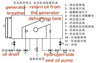
As illustrated in Figure 1, the upper section of the hydrogen-side oil return control box is connected to the defoaming chambers located at both ends of the generator. A vent connection is installed to maintain pressure balance between the tank and the generator interior, ensuring smooth oil return from the defoaming chambers into the control box.
The tank is equipped with two float-operated valves: an oil drain valve and an oil makeup valve. When the liquid level rises above the specified limit, the left-side float moves upward and drives the connecting mechanism to open the oil drain valve. The internal hydrogen pressure then forces oil out of the tank. Conversely, when the liquid level decreases below the required level, the right-side float moves downward and activates the oil makeup valve, allowing oil to enter the tank.
The opening and closing levels of both floating ball valves can be adjusted through level adjustment nuts installed on the connecting rods. To prevent valve sticking or malfunction, manual override valves are also provided for both the oil drain and oil makeup circuits, allowing emergency operation when automatic control fails.
Figure 1. Schematic diagram of the hydrogen-side oil return control box
(Main components: oil drain isolation valve, forced-open oil drain valve, magnetic flap liquid level gauge, float level adjustment nut, forced-close oil drain valve, float-operated oil drain valve, hydrogen-side seal pump isolation valve, float-operated oil makeup valve, forced-close oil makeup valve, oil makeup isolation valve, forced-open oil makeup valve, floating ball.)
1.2 Conventional Manual Inspection Procedure for Floating Ball Valves
Malfunction or incorrect calibration of the automatic oil makeup and oil drain floating ball valves may cause abnormal oil circulation between the hydrogen-side and air-side systems. In severe cases, excessive oil exchange may result in reduced hydrogen purity, increased oil ingress, or hydrogen leakage. Therefore, during major generator overhauls, the floating ball valves must be inspected and calibrated under operating hydrogen pressure conditions.
The conventional inspection procedure includes the following steps:
- Install oil inlet and gas inlet pipelines at the upper flange ports of the hydrogen-side oil return control box.
- Disconnect the downstream pipelines of the oil drain and oil makeup floating ball valves. Install blind plates and ball valves to control discharge flow and observe valve operation.
- Close the automatic function of the oil makeup floating ball valve by operating the forced-close valve, allowing the tank to be filled to a high liquid level for oil drain valve testing.
- Fill the tank with oil through the upper inlet and check the downstream pipeline of the oil drain valve for leakage, preventing excessive oil exchange between the hydrogen-side and air-side systems.
- Gradually increase the oil level until oil begins to flow from the outlet of the oil drain floating ball valve. Record the corresponding liquid level as the valve opening level.
- Add a specified quantity of oil, close the oil inlet valve, and introduce nitrogen through the gas inlet line until the internal pressure reaches the simulated hydrogen operating pressure.
- Open the downstream ball valve of the oil drain valve and observe when oil discharge stops. The corresponding liquid level represents the valve closing level.
- Restore the automatic function of the oil makeup floating ball valve and verify whether the valve remains leak-free under normal conditions.
- Open the oil drain override valve to lower the tank liquid level. When oil begins to flow from the oil makeup valve outlet, record the liquid level as the opening level of the oil makeup valve.
- Remove nitrogen and oil from the tank, adjust the float position according to the calibrated values, and repeat the testing process to confirm accuracy.
Although effective, this manual procedure requires repeated oil filling, draining, pressurization, and visual measurement. It is highly dependent on operator experience and can introduce measurement errors.
2. Operating Principle of the Automatic Floating Ball Valve Detection Device
Due to the complicated maintenance procedure and elevated installation position of the hydrogen-side oil return control box, conventional manual inspection places a significant workload on maintenance personnel. In addition, repeated oil discharge and nitrogen venting operations may create environmental contamination risks during maintenance.
During liquid level calibration, sensor signals are usually transmitted to the Distributed Control System (DCS), while technicians rely on magnetic flap liquid level gauges for visual confirmation. This combination of manual observation and indirect measurement may result in calibration deviations. Therefore, an automated detection and calibration system is required to improve testing efficiency and accuracy.
Figure 2. Field installation of the hydrogen-side oil return control box
The automatic floating ball valve detection device was developed according to the existing manual maintenance procedure. The system automatically performs oil filling and gas pressurization operations according to a preset testing sequence, eliminating the need for repeated manual intervention.
The oil supply and gas charging pipelines are equipped with electrically controlled valves to regulate flow and isolate the system. Dedicated return-flow detection pipelines are installed downstream of both the oil makeup and oil drain floating ball valves. Flow sensors installed on these pipelines detect oil movement and determine whether each floating ball valve is in an open or closed state.
During testing, the Programmable Industrial Controller (PIC) coordinates pumps, valves, and sensors to complete the entire inspection process automatically. Pressure and flow data are continuously collected and analyzed to calculate the precise opening and closing liquid levels of the floating ball valves. After testing is completed, the device automatically recovers the oil inside the system, eliminating manual draining operations.
The proposed automatic detection device significantly improves inspection accuracy, reduces maintenance workload, shortens overhaul time, and provides a safer and more reliable method for floating ball valve calibration in turbine generator seal oil systems.
China manufacturer offers high-quality industrial products with competitive pricing and advanced production capabilities.

 English
 Arabic
 Français
 Español
 Português
 Deutsch
 Türkçe
 Italiano
 Russian
 Romaian