


How Can the R9M60 Wireless Energy Sensor Reveal Hidden Load Patterns?
Why Is a Circuit Baseline More Useful Than a Single Reading?
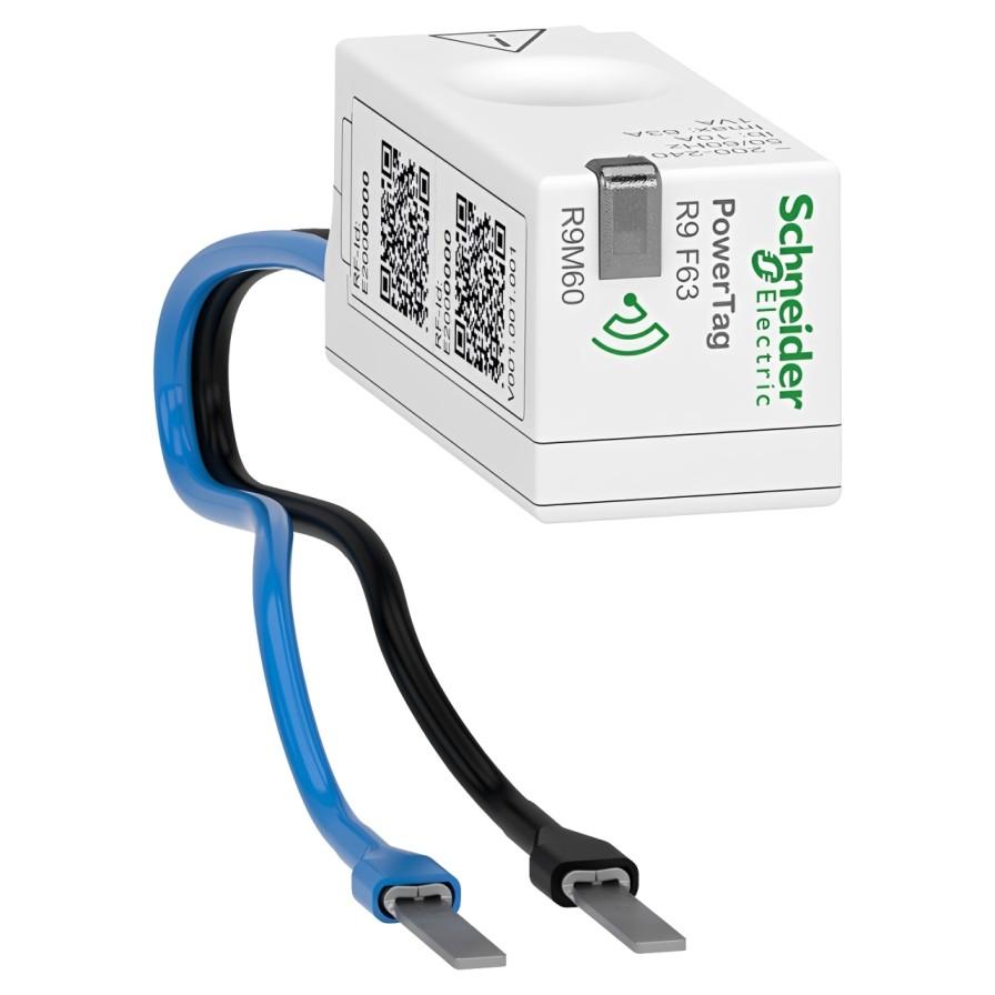
Within a connected electrical system, the R9M60 Wireless Energy Sensor helps users understand how an individual circuit behaves over time. Designed for association with compatible Circuit Breakers and a Wiser gateway, MPN R9M60 monitors a 1P+N circuit rated up to 63A and transmits the collected information wirelessly.
A single measurement only shows what was happening at one moment. A circuit baseline captures normal behaviour across working hours, overnight periods, weekends and changing seasons. Once this baseline is established, unusual activity becomes easier to recognise because it can be compared with a known operating pattern.
The sensor does not decide whether energy use is acceptable. It provides structured information that allows building occupants, facilities teams or electrical professionals to investigate changes with better evidence.
What Creates a Circuit Load Profile?
A load profile shows how demand changes over a selected period. Lighting may produce predictable peaks at opening and closing times, while heating equipment may cycle according to temperature. Refrigeration, pumps and ventilation systems can create repeated operating patterns that appear clearly when data is reviewed over several days.
The R9M60 Wireless Energy Sensor provides circuit-level information rather than relying only on a property’s total electricity consumption. This distinction matters because several smaller loads can be hidden within one overall reading. Separating a selected circuit makes it easier to understand its contribution.
Meaningful analysis requires context. Working schedules, weather, occupancy, maintenance activities and production changes should be recorded alongside the data. Without this information, a normal operational increase could be mistaken for an energy problem.
How Can Unusual Load Patterns Be Identified?
An unusual pattern may appear as higher overnight demand, longer operating periods or repeated consumption when a circuit should normally be inactive. These changes can indicate altered schedules, additional equipment, persistent standby loads or a control setting that requires investigation.
The R9M60 Wireless Energy Sensor can help narrow the search to a specific circuit, but its readings do not prove the cause of a change. An electrician or facilities professional may still need to inspect connected equipment and complete suitable tests.
Short-duration events should be interpreted carefully. Motors, heaters and power supplies may draw differently during start-up. A repeated change across several comparable periods is generally more informative than one isolated peak.
Why Does Accurate Circuit Naming Matter?
Useful data depends on correct identification. Labels such as “Circuit 7” may match the board schedule, but they provide little immediate meaning to someone reviewing a dashboard. Descriptions such as “first-floor lighting” or “workshop extraction” make patterns easier to interpret.
The installer should confirm the physical circuit, sensor identity and gateway record before monitoring begins. If two wireless sensors are assigned to the wrong names, later decisions may be based on misleading information even though both devices are measuring correctly.
Changes to the installation must also be documented. When circuits are extended, reassigned or combined, the monitoring label and baseline should be updated. Historical comparisons are only reliable when the monitored load remains clearly understood.
How Is Energy Monitoring Different From Electrical Protection?
The R9M60 Wireless Energy Sensor measures and communicates electrical information, but it does not disconnect a dangerous fault. In organised Distribution Boards, overcurrent and short-circuit protection remains the responsibility of correctly selected protective devices. Suitable Residential RCCBs provide residual-current protection where required, but they perform a different function from energy monitoring.
A sensor reading that appears normal does not confirm that an installation is electrically safe. Earthing, insulation, conductor condition and protective-device operation require appropriate inspection and testing.
Similarly, a high energy reading does not automatically indicate an electrical fault. It may simply reflect legitimate demand. Monitoring data should support professional judgement rather than replace electrical safety procedures.
When Would Current Transformer Monitoring Be Considered?
Systems based on Current Transformers can be appropriate for larger conductors, higher-current installations, multi-phase systems or equipment designed around separate metering components. These arrangements may provide greater flexibility, but they can require additional wiring, panel space and compatible measuring equipment.
The R9M60 Wireless Energy Sensor offers a different approach. Its compact format is designed for compatible 1P+N protective devices rated up to 63A, while wireless communication reduces the need for dedicated data cabling.
Neither method is universally better. Selection depends on conductor arrangement, circuit rating, board compatibility, available space, communication requirements and the level of data required.
Where Do Panel Meters Fit Into the Monitoring Strategy?
Professional Digital Panel Multi-Function Meters can provide local readings and measure several electrical parameters within larger control or distribution systems. They may be preferred when operators require an immediate display at the panel or integration through a particular wired protocol.
The R9M60 Wireless Energy Sensor is more focused on compact, connected circuit monitoring through a compatible gateway. It is particularly useful where information needs to be reviewed remotely through the associated system instead of only at the electrical board.
A facility may use different monitoring approaches at different levels. A main incomer can provide an overall reference, while selected circuit sensors reveal which loads are responsible for changes.
How Should Historical Data Be Interpreted?
Useful comparisons should cover similar operating conditions. Comparing a winter heating circuit with a summer week may reveal seasonal behaviour, but it will not provide a fair short-term performance comparison. Weekday data should normally be assessed against equivalent weekdays with similar occupancy.
The R9M60 Wireless Energy Sensor can support verification after an operational change. If lighting schedules are adjusted or older equipment is replaced, readings before and after the change can show whether consumption patterns actually improved.
Data should be retained long enough to reveal recurring behaviour. Daily review helps detect sudden changes, while monthly and seasonal analysis provides a broader understanding of demand.
What Can Affect Wireless Communication?
The sensor must communicate with a compatible Wiser gateway or concentrator. Metal enclosures, board construction, building layout, gateway position and radio interference may influence communication quality.
Before final commissioning, the installer should confirm that the sensor remains visible to the gateway while the board cover is fitted and the electrical room is in its normal condition. Successful pairing with an open enclosure does not automatically guarantee reliable operation after the installation is closed.
The listed 10mW power consumption relates to the sensor itself. The complete monitoring system also requires the compatible gateway, network connection and software environment necessary to receive and present the information.
What Must Be Verified Before Installation?
A competent electrician should confirm compatibility with the selected protective device, the 1P+N conductor arrangement, the mounting position and the circuit’s maximum current. The 63A rating is an upper limit, not a recommendation that every monitored circuit should operate continuously at that value.
Power must be safely isolated and proved dead before work begins. Terminal preparation, conductor placement, tightening torque and mounting orientation must follow the manufacturer’s instructions. The circuit should then be clearly labelled and tested before being returned to service.
With correct installation and thoughtful interpretation, the R9M60 Wireless Energy Sensor can transform an isolated electrical circuit into a useful source of operational evidence. Its compact design, wireless communication and circuit-level visibility help users recognise hidden patterns, validate improvement measures and make more informed energy-management decisions.

 English
 Arabic
 Français
 Español
 Deutsch
 Türkçe
 Dutch
Dutch
 Italiano
 Russian
 Romaian